|
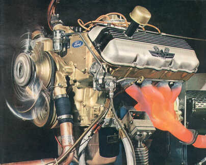
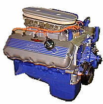
The Cammer was based on the 427 side-oiler block with cross-bolted main
bearing caps. This block was shared with the normal production 427 (if you can
call any Ford 427 a "normal production" engine). It differs in two ways, however.
A cast boss and drilled passage through the water jacket at the rear of the block
drained oil from the cylinder heads. Since an accessory driveshaft is used in
place of the normal camshaft, only bearing locations #1 and #2 are used. The remaining
three locations are fitted with steel bushings to seal off the lubrication system
and provide oil passages to the overhead valve train.
The crankshaft and vibration damper are shared with the production 427.
Heavy duty LeMans style connecting rods are required to survive continuous
high speed operation. These rods utilize a cap screw rather than the normal
bolt and nut to attach the cap. Alignment is maintained by dowel sleeves
surrounding the screws in counterbores. The cap screws are 12-point head, integral
washer, and have an undercut shank. A tri-lobe interference thread is used
to more uniformly spread the bolt loads along the entire length. These bolts may
be used only one time. The piston pins
are full-floating, with a bronze bushing in the connecting rod small end. The pins
have non-uniform thickness, putting material where it is most needed and at
the same time saving weight. Close tolerance is maintained between the ends
of the pins and the snap rings to prevent unwanted hammering by the pin.
The pistons are slipper skirt aluminum alloy, machined by a contour cam
grinder. This operation leaves the proper oval shape (at room temperature)
and a grooved or threaded surface finish to hold oil. 1/16" thick compression
rings are used, of a chrome plated barrel shape. A normal oil scraper type
oil ring is used. The rings are of a low tension design, further reducing
friction. Large domes with flattened valve clearance areas provide high compression.
Entirely new heads featured hemispherical combustion chambers with
large valve encourage high volumetric efficiency over a broad rpm range.
One overhead camshaft per cylinder bank operate the valves through roller-follower
rocker arms. These are shaft mounted and are designed for high speed operation with
minimum friction. The cylinder heads and block retain the standard FE family
bolt pattern. To accomplish this, internal support pillars are cast into the
heads. The camshaft bearing and rocker shaft supports are cast into the heads.
The SOHC camshaft arrangement allowed the use of a wide angle between the intake
and exhaust valves, approximating a hemispherical combustion chamber. The
chambers are fully machined to closely control their volume. The spark plugs
do not enter the center of the chambers, but rather enter from the intake side.
This was done to use shorter spark plug wires and make the plugs more accessible.
The cam bearings use saddle caps, similar to crankshaft main bearing caps.
They are align bored, and fitted with normal babbit lined split inserts.
Due to sharing a common cylinder head between left and right banks, and the
layout of the cam lobes and followers, results in five bearing journals
on the left bank, and six on the right.
The intake and exhaust valves are larger than those found on the 427 production
engine. The exhaust valves feature a sodium filled hollow stem for better heat
conduction. Dual valve springs are used, the inner spring being an interference
fit within the outer spring. Valve lash is adjusted by select fit valve stem caps.
|
|
The normal timing chain ran to an idler shaft in place of the normal camshaft.
This shaft continued to drive the distributor and oil pump. A sprocket
on this shaft drove a second timing chain a whopping 6 feet long which snaked around
the camshafts and various idler wheels. The accessory shaft is further
supported by a ball bearing in the front cover. Due to oscillations in the
long timing chain at speed, it proved difficult to time the camshafts.
Operation in excess of 7000 rpm also taxed the oiling system, but clever
engine builders found solutions to the problems.
The engines featured a transistorized ignition system, triggered by a
dual low-mass tungsten contacts in the distributor. The amplifier directs
12 amperes to a special coil to provide hot sparks at all engine speeds. The centrifugal
advance mechanism provided 30 degrees maximum advance. The spark plugs fit
deeply into the cylinder head, in a well formed of copper tube. This seals
oil within the head and further acts as the spark plug gasket.
As supplied by Ford, the 427 SOHC used a 7-1/2 quart oil pan with a baffle
windage tray to scrap oil off the crankshaft. The oil pump pickup is
additionally secured to a boss in the block enabling it to withstand severe
vibration. 20.5 gallons of SAE 40W per minute at 70 psi is provided by the oil pump.
A special spin-on filter was used to handle the high volume of this oiling system.
Oil pumped through a passage in the cylinder head deck (common to all FE family
engines) is used to lubricate the camshaft bearings, rocker shafts, and follower
tips.
The 427 SOHC was virtually built by hand, and was initially intended
for stock car racing.
The addition of hemispherical chambers and overhead cams transformed
the 427 wedge into a very serious powerplant. Factory ratings were
615 hp @ 7000 rpm with a single 4-barrel, and 657 hp @ 7500 with dual carburetors.
The engines weigh 680 lbs.
These engines were sold over the Ford parts counter.
Ford recommended blueprinting the engines before use in racing applications.
4V model C6AE-6007-363S, 8V model C6AE-6007-359J, $2350.00, October 1968.
Though Ford sold the required number of units to homologate the design,
the Cammer was prevented from running against the Chrysler
hemi at Daytona in 1965 due to NASCAR rule changes.
Many Cammers found their way into Mustangs running A/FX
Factory Experimental drag racing.
|


